
FEATURES:
- Embedded Software Architecture
- High frequency Data Acquisition & Processing
- C++ code experience
- Custom Serial Communication Protocols & Byte Steam Handling
OVERVIEW:
This project was developed as part of my universities Senior Design project, where groups of students are assigned to a specific sponsor's project and given two semesters to design, assemble, and test their solution.
NASA JPL tasked our group with developing a testbed and vibrating end effector aimed to minimize lunar excavation forces. The project aimed to provide meaningful modelling data about the dynamics of specified vibrational inputs, frequency responses, and measured excavation forces across a range of different testing conditions.
MECHANICAL:
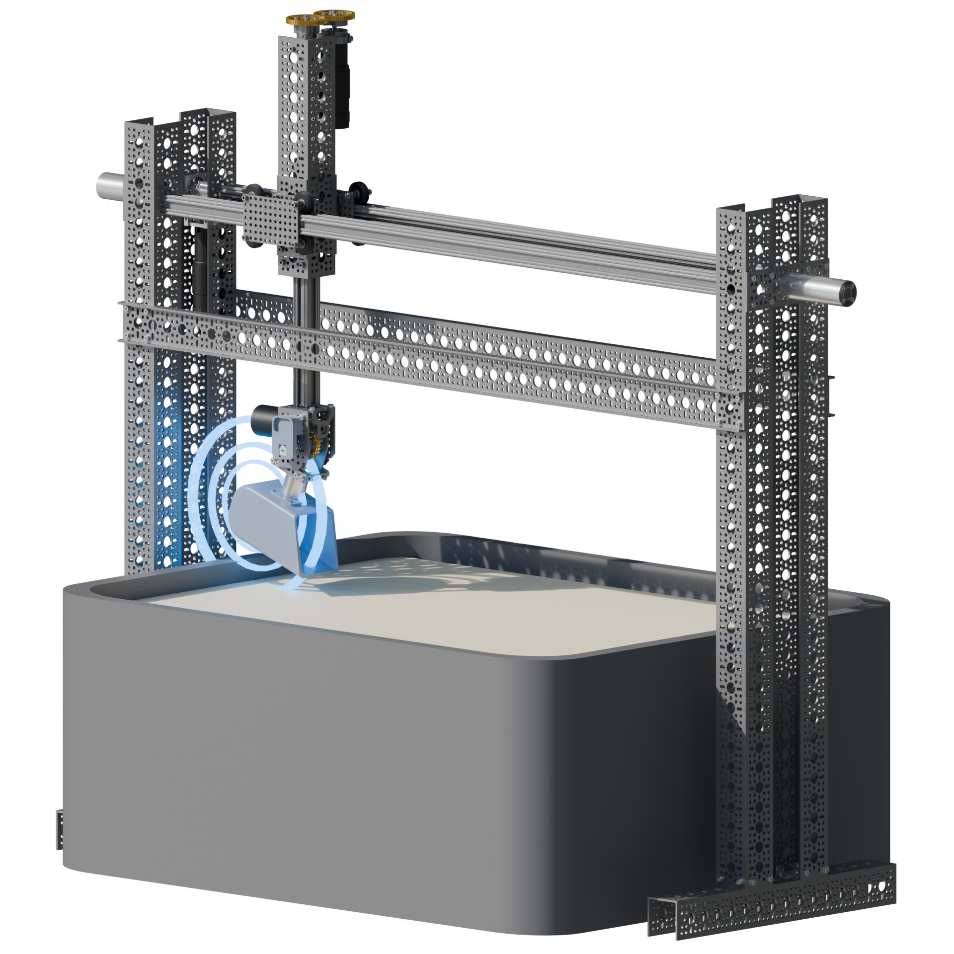
The system features a simple mechanical design, consisting of a 3-degree-of-freedom (3DOF) kinematic chain with two translational inputs (X, Y) and one revolute (pitch) input to precisely control the position and orientation of the end effector. The system is designed to withstand forces of up to 100N in both horizontal and vertical directions. To achieve high mechanical advantage and enhanced precision, lead screws were selected for the horizontal and vertical translational stages, while a worm gear drive was implemented for the rotational stage. These transmission choices ensure efficient force transmission, improved load capacity, and reliable operation.
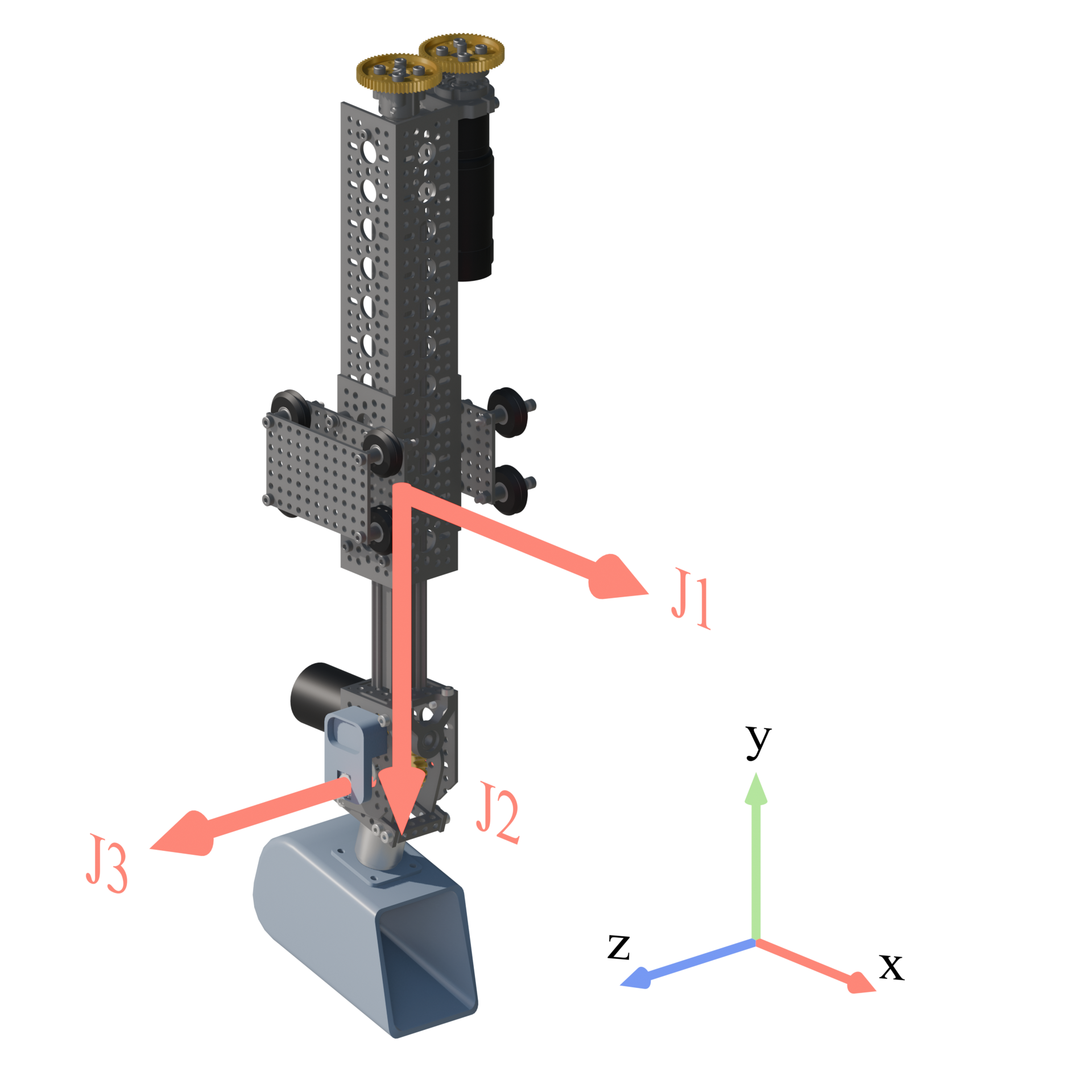
Joint Structure / Frame Notation
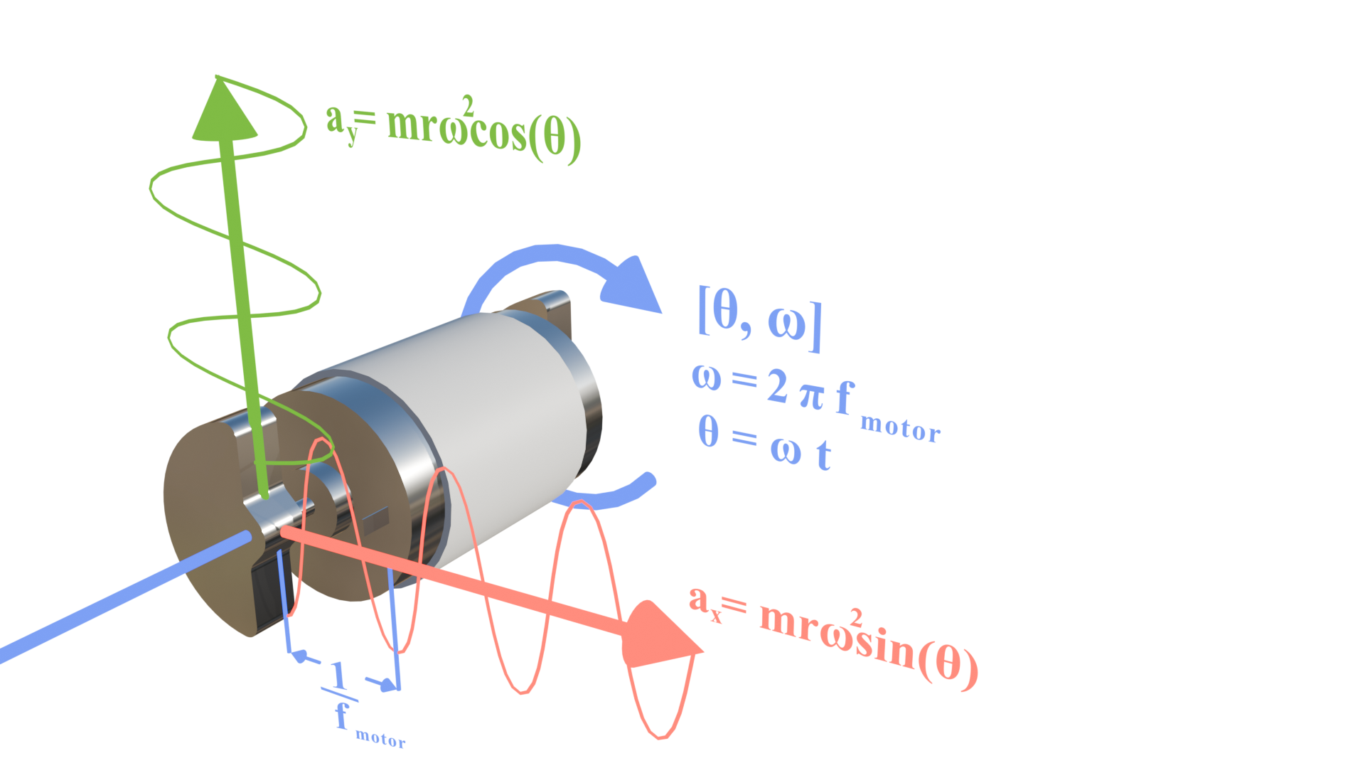
Vibration Motor
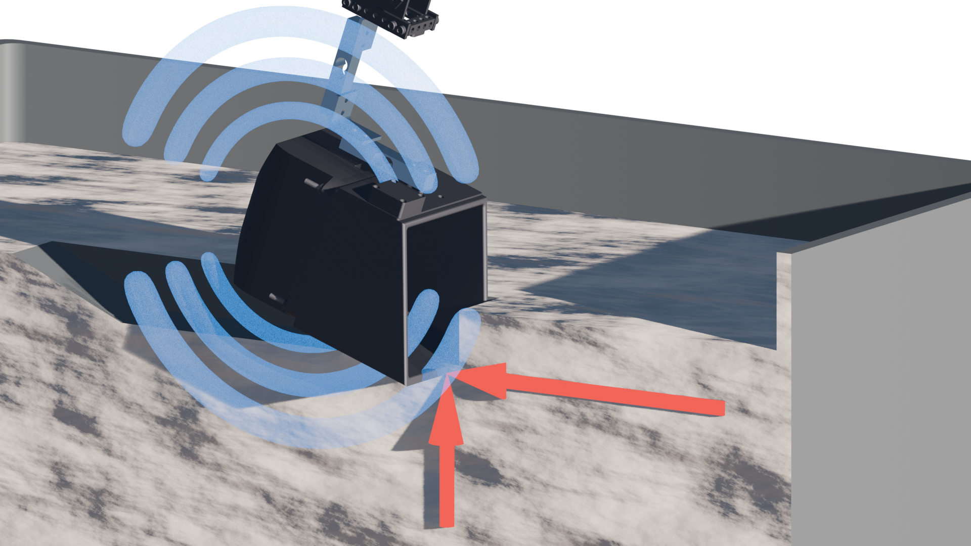
Excavation Forces (Red) Vibration outputs (Blue)
The end effector design is very robust, containing the primary vibration motor along with force and acceleration instrumentation. The vibration motor can be oriented in two different directions to produce vibrations in either the xy or xz plane. The force feedback system was initially hoped to be a 6DOF force torque sensor, but budget restrictions required a simplified pair of cantilevered load cells to produce the necessary force output signals.
Demonstration Video
SOFTWARE:
Architecture
The full source code for this project can be found here on GitHub. For this project, I aimed to explore a more structured approach to software architecture. While I had prior experience with C, I wanted to experiment with C++. I also was able to integrate a considerable amount of Blender 3D into the workflow for trajectory and movement generation.
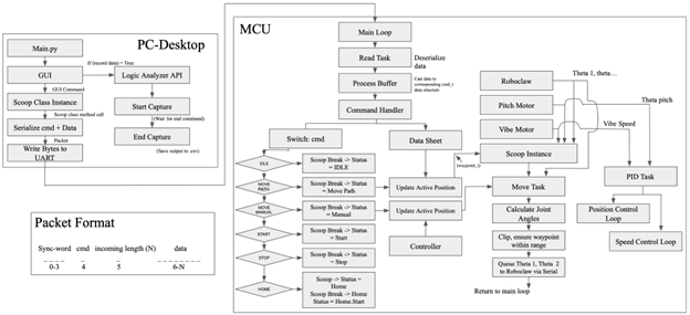
Software Controls Chart:
An Arduino Mega was chosen as the primary MCU for its ease of setup. However, this came with a trade-off in performance, which became a slight challenge later on.
The system has two primary functions (1) Position Control, and (2) Sensor Feedback
Since these tasks run synchronously, a cooperative multitasking approach was used to avoid blocking the main loop. Each task was separated into individual code modules designed to execute quickly and efficiently.
The system is structured around two main classes:
SerialPacket – Handles serial communication
Scoop – Manages movement and control commands
In the main loop, tasks run in the following sequence:
SerialPacket.read_task() // Read incoming commands
Scoop.command_task() // Process scoop commands
SerialPacket.write_task() // Send data back
Classes
SerialPacket Class
This class stores is responsible for reading/writing data with the host. The class stores the current state of data transfers along with incoming packet sizes, syncing data, and the data buffers themselves.
The .read_task() function processes incoming binary serial command packets from a Python script running on the host. The incoming bytes are stored in a buffer and parsed using a state machine to prevent blocking. Once the DATA_COMPLETE state is reached, an internal process_command() function decodes the packet. The command byte determines which command_t struct the data belongs to, enabling a modular and scalable command-handling approach.
The .write_task() function formats the outgoing data in a return packet and sends the data_t packet back to the main py file where it is unpacked and stored on the host for later data analysis.
Scoop Class
This class manages the position, vibration, and sensor calls of the system. This scoop class communicates with the motor drivers and position feedback sensors to control the current position and orientation of the scoop. The x/y positions are controlled via a serial Roboclaw motor driver board, which contains built in PID handling and position control. Position/velocity/accel setpoints are sent serially from the MCU to the driver board where it handles these movements. The pitch motor is handled manually with a PID controlled position loop. The vibration motor speed is controlled with a simple PWM duty cycle output across an H bridge. This duty cycle is proportional to the vibration motor speed, allowing for a model of the current system input.
The .command_task() function is responsible for updating position setpoints, handling homing routines, and executing commands such as start, stop, etc.
Trajectory Generation
Blender's 3D environment was used to provide a robust and customizable 3D environment for trajectory planning and visualization. The internal kinematic tools were used to create a 1:1 virtual mesh of the system with corresponding joint axis and limits. These constraints helped ensure any generated waypoints would be within the workspace of the physical system and avoid collision issues with any supporting structures. A side-by-side of the blender trajectory and the physical system is shown below.
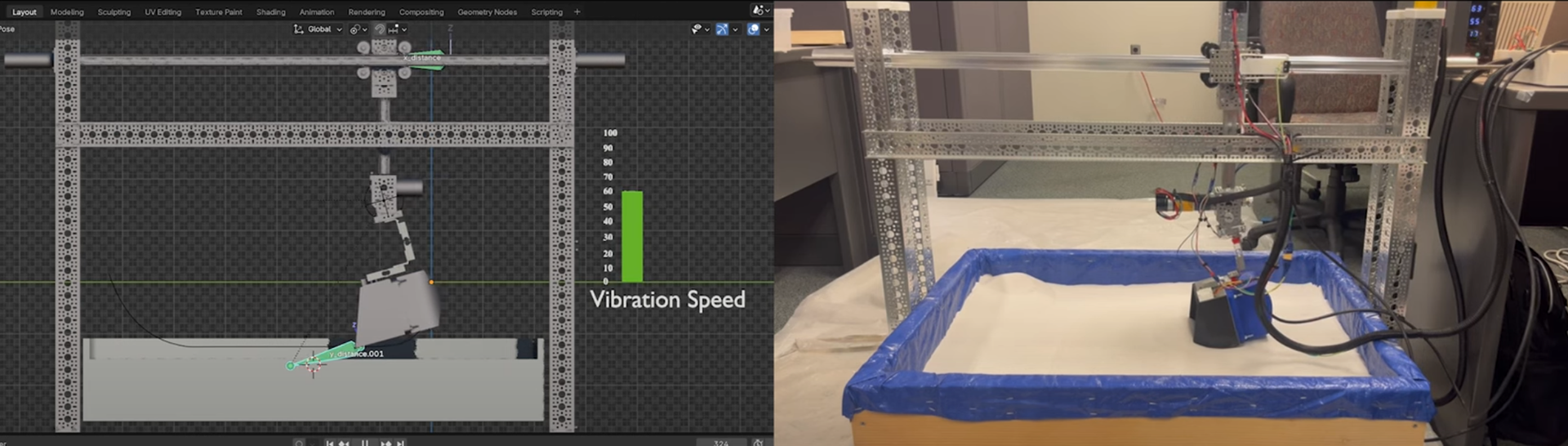
Trajectory Planning
Blender's 3D environment was used to provide a robust and customizable 3D environment for trajectory planning and visualization. The internal kinematic tools were used to create a 1:1 virtual mesh of the system with corresponding joint axis and limits. These constraints helped ensure any generated waypoints would be within
HARDWARE:
The primary instrumentation devices used are the load cells for force measurements and an accelerometer for acceleration and frequency response measurements. The vibration motor provides up to 1.2kHz vibrational inputs to the system, thus a sampling frequency of at least 10x this (10-12kHz) was required to properly analyze the frequency responses.
Loadcell/Amp
The loadcells were originally designed for use with an HX711 24bit ADC, however this device has a max sampling speed of 80Hz which was considerably lower than needed. Thus, an alternative INA125P instrumentation amplifier was used. This device is a low power high accuracy amplifier with a precision voltage reference and a single analog voltage output. The gain bandwidth product of this IC is 450kHz. Providing significantly higher frequency ranges than the HX711.
Accelerometer
The accelerometer selection depended on both the sampling frequency and the sensing range. Given a sampling range between 10-12kHz and a maximum amplitude of 10g's the 590C tri-axial accelerometer was chosen. The device is capable of sensing ranges up to 50g's with a frequency range up to 15kHz. This device also provides direct analog voltage outputs for each axis, eliminating the need for any I2C or SPI communication calls.
RESULTS:
TESTING PLAN
Different testing procedures were performed with the system with various testing parameters (scoop velocity, vibration speed, excavation depth, soil compaction, motor orientation).
- Scoop velocity and excavation depth were controlled by adjustment of Blender waypoint trajectory
- Vibration speed controlled though varying duty cycles on the vibration motor driver
- Soil compaction split into loose (1) and compact (2) categories, and compaction routine was developed to ensure accurate and repeatable results.
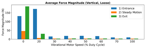
DATA ANALYSIS
The excavation cycle was split into three distinct regions. The entrance region (blue), steady state motion (orange), and the exit region (green). The force measurements in each of these regions varied considerably due, with large force spikes in the entrance and exit regions.

Excavation Regions
Force outputs
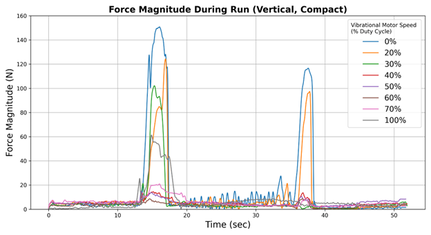
Raw Force Plots