Features:
- End-to-End Mechatronics System Development
- Precision Mechanism Design & Kinematics
- Embedded C Development in GCC & Makefile Environments
- STM32 Microcontroller Firmware Development
- Real-Time High-Speed Control System Implementation
- USB Bulk Data Transfer & Communication
OVERVIEW:
Robotic Assisted Surgery (RAS) requires precise instrumentation to translate the surgeon's hand gestures into the movement of a surgical robot. The surgeon's movements should feel smooth and effortless, with the device acting as an extension of their hands. Haptic feedback controllers help bridge the gap between the physical and digital spaces. This specific hand controller functions as a back-drivable serial robotic linkage.
The controller has three primary functions. First, it continually measures the state of all joint angles and converts these values into a global spatial representation (x, y, z, roll, pitch, yaw). These six parameters are then used to control the position and orientation of the surgical robot. Second, the controller is gravity compensated, using torque controllers on the motors. This type of control results in a weightless feeling where the output grip can be easily moved to any position and released, and the grip will maintain its current position. Lastly, the controller is capable of providing haptic feedback to the user in the form of directional force commands. These forces can be used to simulate contact feedback or to provide virtual workspace boundary limits.
KINEMATICS:
Initial design work began by first by characterizing the ideal workspace and force outputs. These constraints helped provide a starting point for motor selection and general project scale. The Force Dimension lambda.7 controller was used as a starting point to determine initial link lengths and joint limits. An equivalent serial workspace was developed and created with the following serial kinematic layout.
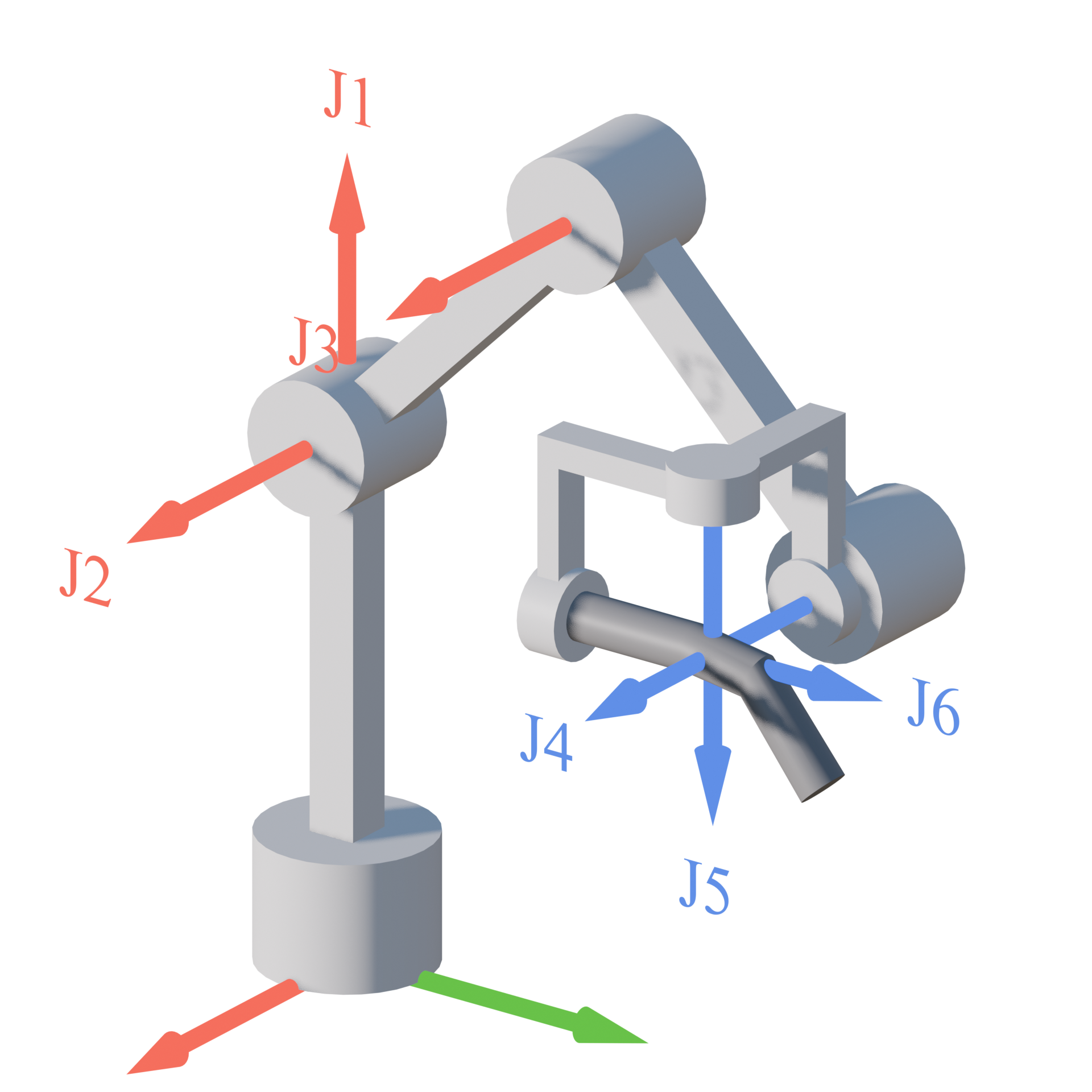
Kinematic Structure:
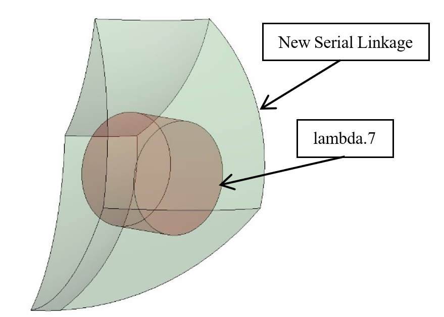
Workspace Comparison:
To determine the necessary motor sizes, a joint torque analysis was performed on the system. This was performed by computing the analytical Jacobian matrix J of size N, where N denotes the number of joints. The required joint torques were split into two components: (1) the components required for gravity compensation, and (2) the component required for a specified end effector output force. The required joint torques for gravity compensation were calculated individually per link using the following equation. Where τi denotes the required joint torque for gravity compensation, F denotes the applied force or weight, r denotes the vector from the axis of revolution to the location of the applied and z denotes the unit vector which points in the direction of rotation.
τi = r x F ∘ z
The required joint torques necessary for the end effector force output was found using the more general Jacobian notation, where τ represents an array of torques of size N, JT represents the transpose of the Jacobian matrix, and F is a 3D vector denoting the components of tip force.
τ = JT F

Forward Kinematics / Torque Model: Nominal Pose

Forward Kinematics / Torque Model: Arbitrary Pose
MECHANICAL DESIGN:
Motor Selection
Motor selection was a key constraint in for the design. Brushless motors initially appeared the obvious choice due to significantly higher torque output over brushed motors, however these provide unwanted 'cogging' effects due to interaction of the rotor magnets and stator teeth, causing intermittent 'steps' during rotation. To make the movements as fluid as possible, pancake brushed motors were chosen for the primary drive motors. These provided lower torque outputs, but could be back-driven much more smoothly.
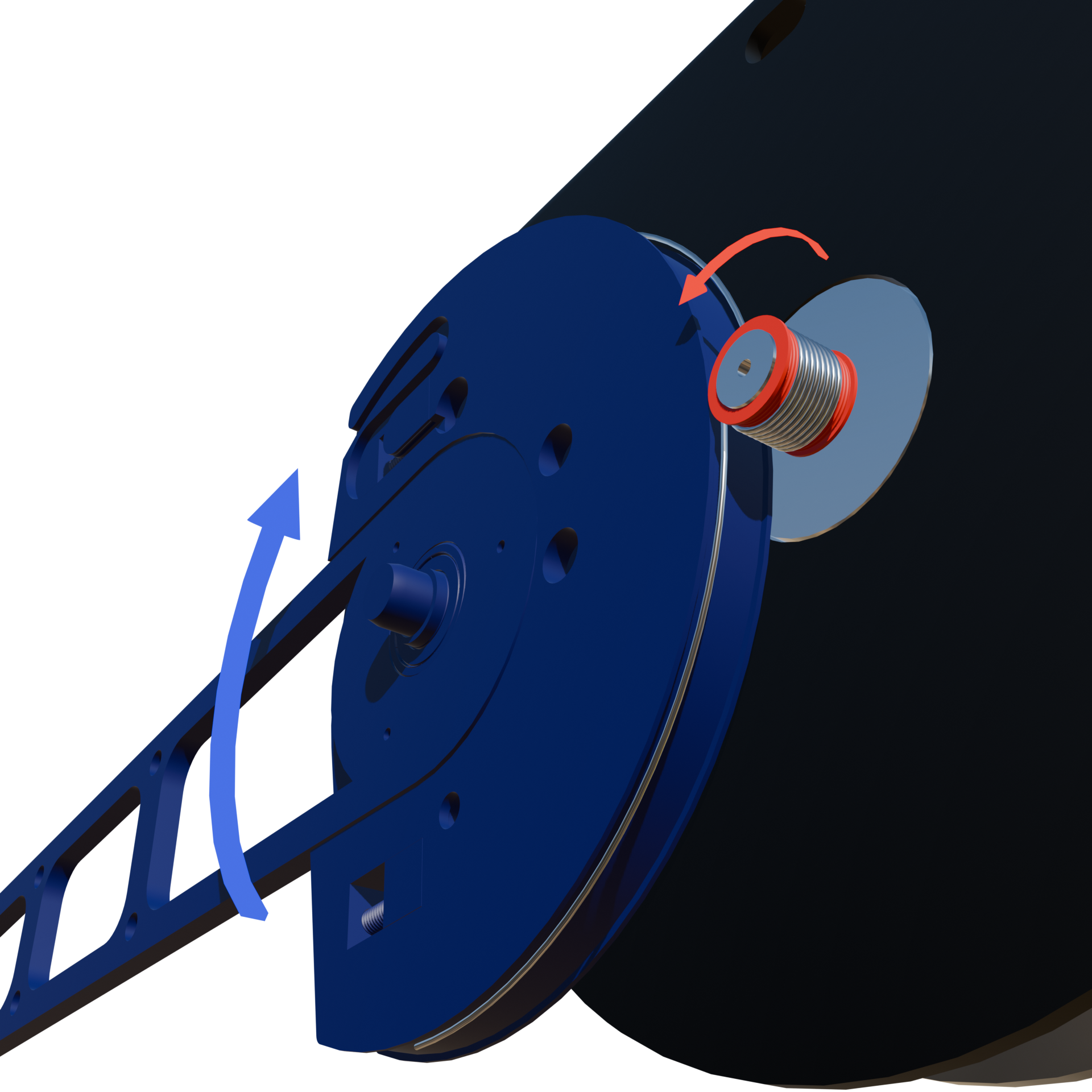
Capstan Drive
To compensate for the lower torque motors, a reduction stage was required to increase torque output, Traditional geared reducers produce unwanted backlash and inertia. An alternative Capstan design was instead chosen. These drives are employed on the three primary joints J1-J3 as they required the highest torque outputs. Each drive follows a similar design, as shown in the figure below. The capstan employs a stainless steel wire rope wound around a smaller diameter sheave (red) and terminated at both ends on the output pulley (blue). This configuration provides a gear reduction ratio of 10:1, based on the ratio of the diameters. The primary design constraint was the output torque, estimated to range from 10-15 Nm. This constraint informed the selection of wire thickness, the number of turns on the sheave, and other relevant parameters for the wire-based components.
Torque Controlled Capstan Demo
Capstan Mechanism
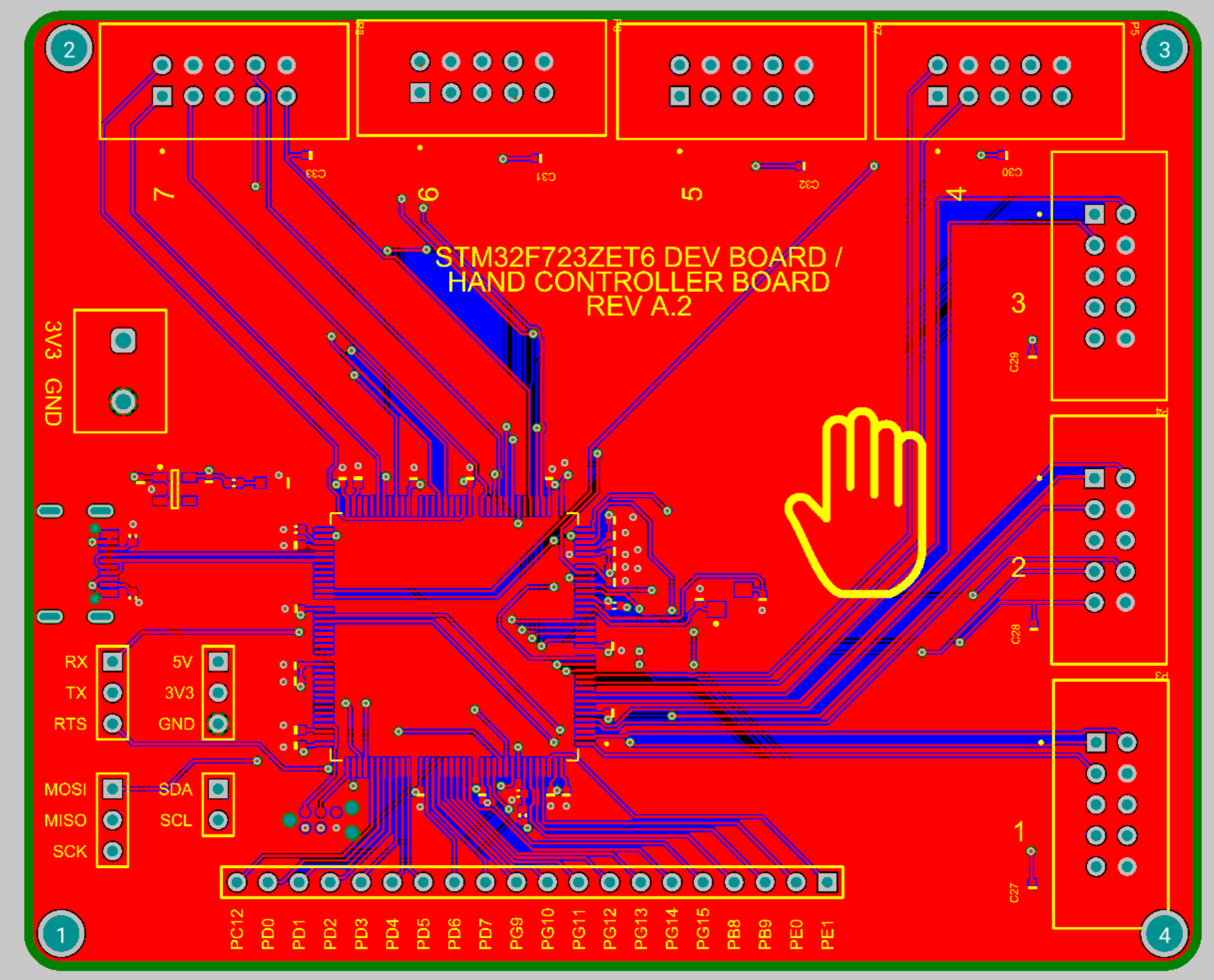
MCU Board
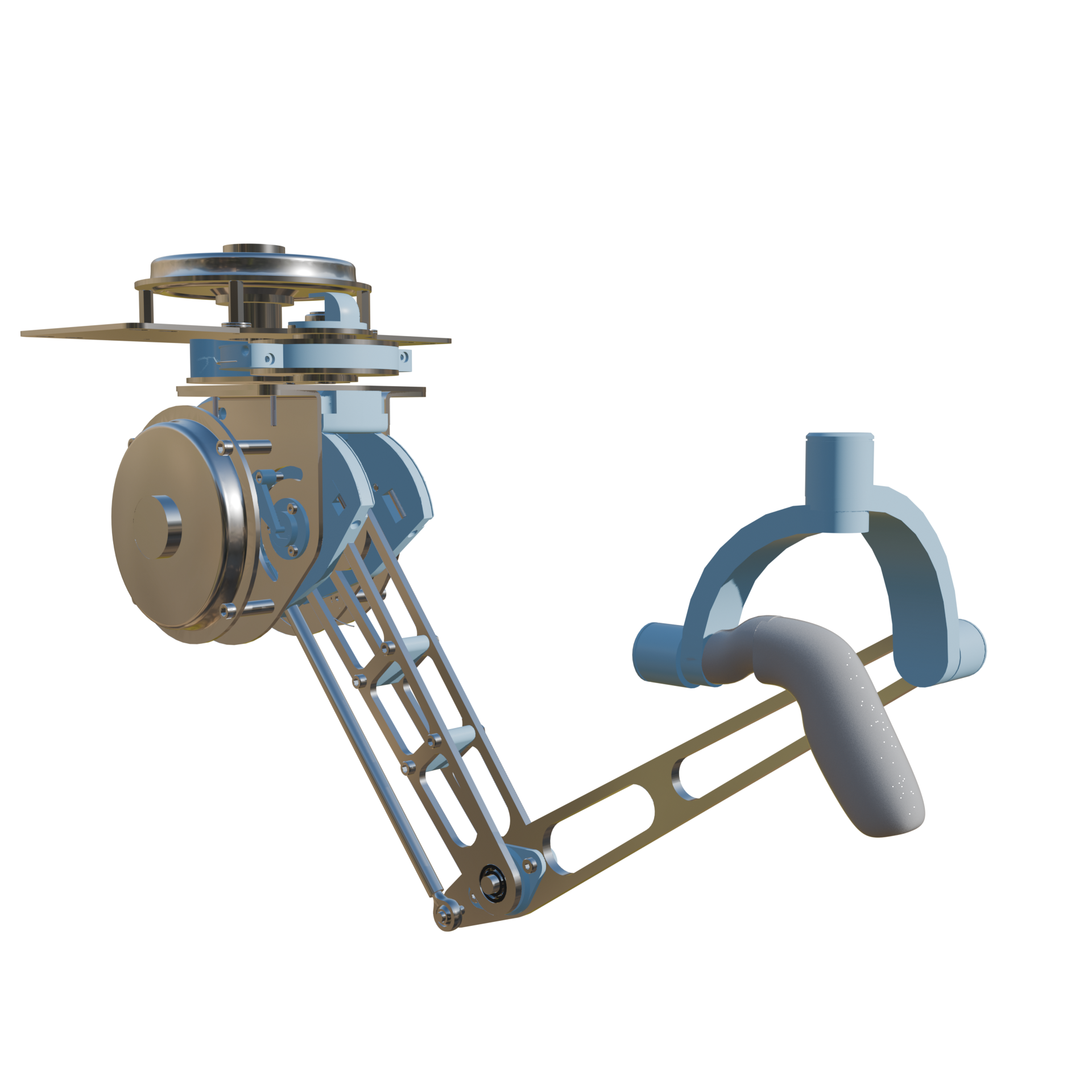
Assembled Design
The final design is shown below (left). The motors were placed as close together as possible to minimize unwanted inertial effects. This is most notable in the lower parallel linkage that drives the J3 motor.
DFA and DFM considerations were made to make the parts easy to produce and assemble. The current controller is produced from low-cost 3D printed and laser cut parts, allowing for quick prototyping and repairs. The most complex feature, the capstan, can be easily accessed by disassembling the controller into its separate modules (right). This allows for easy winding and tensioning of the drive.
Assembled View
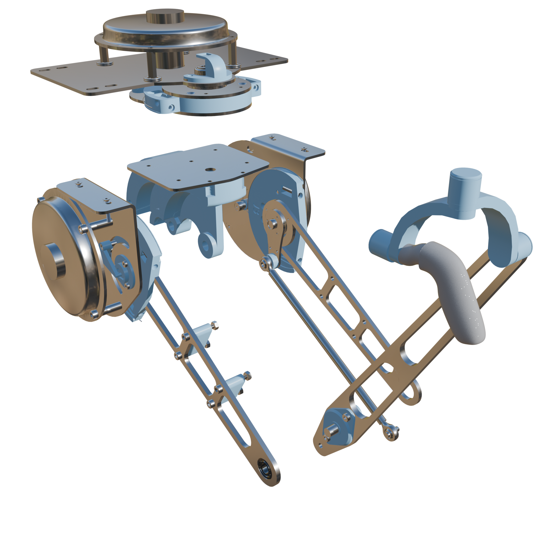
Exploded Module View
Gravity Compensated Controller Demo
MECHATRONICS
Embedded Systems
The system is controlled by an STM32F7 microcontroller with a Cortex-M7 32-bit ARM processor, running at 216 MHz. The MCU is responsible for handling PWM outputs, ADC conversions, and USB data transfers.
PWM outputs are generated at 20kHz frequency off of an internal timer, and this timer is also used to trigger raw ADC signal conversions. When the timer event occurs, a multichannel ADC conversion is kicked off and the raw values are sent directly to memory via a DMA buffer. This helps ensures a constant sampling rate that remains in phase with the PWM signal to prevent timing mismatches while also minimizing CPU overhead.
The primary ADC signals themselves are joint angles and motor current draw. The joint angles are measured from rotary potentiometers whose output voltages change proportionally with the output angle of each link. The motor current signal comes from the Allegro A4956 motor driver chip. This chip is responsible not only for controlling the motor gate bridge outputs, but also provides a voltage output proportional to the load current, which is calibrated using a sense resistor. To minimize noise, an RC low pass filter is applied to the final output signal before being captured by the ADC.
Control Systems
In order to control motor output torque, a current control loop is required. Torque and current are proportional, and the output torque can be directly related to the measured current draw through the motor torque constant K. The motor driver's PWM output is controlled with a simple PI loop based off of a given current setpoint and measured current input. This control structure is shown below.
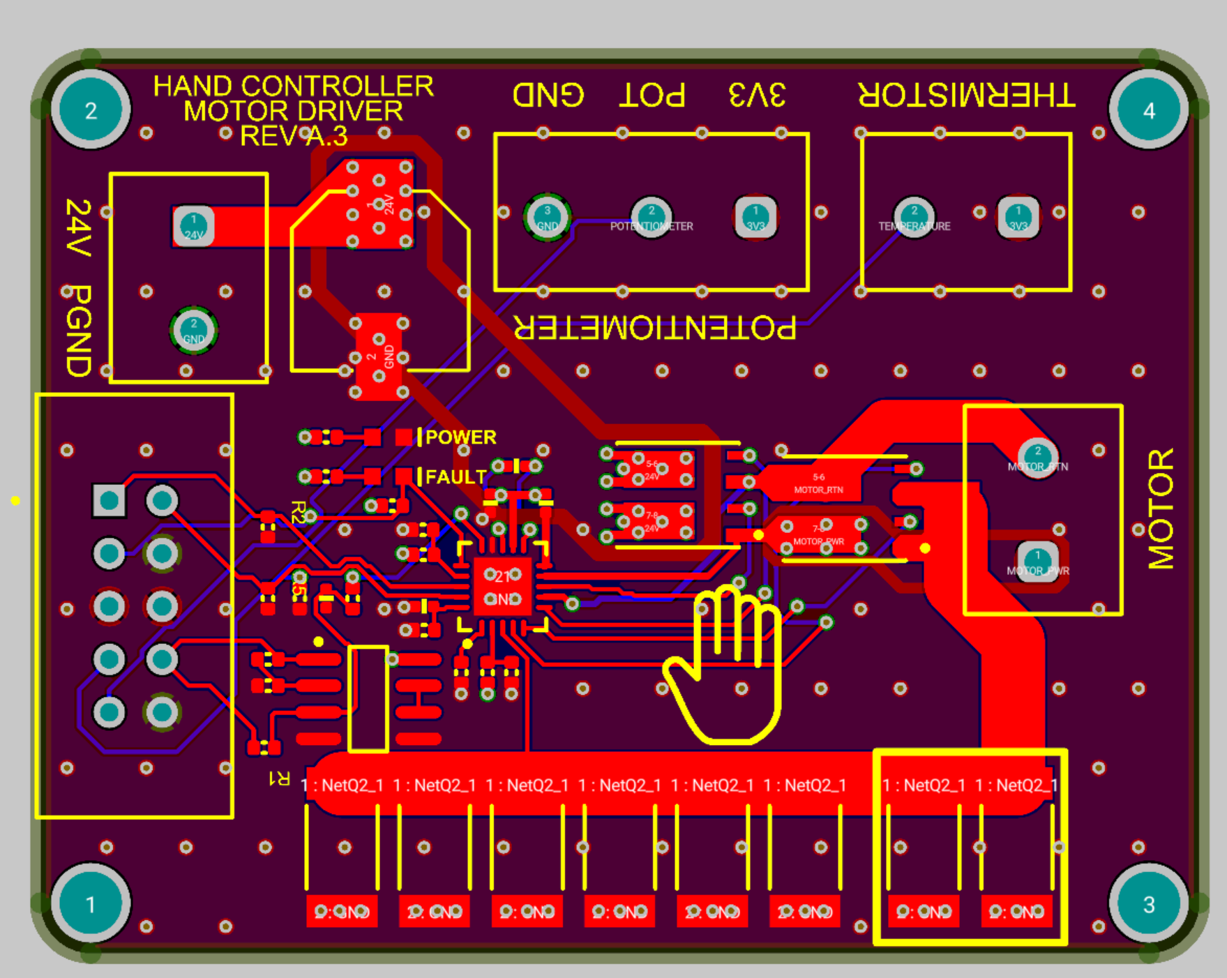
Motor Driver Board
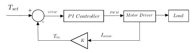
Torque Control Loop
In software, each motor has a dedicated PID object which handles controlling the output PWM. Each motor is tuned individually and a calibrated with an external digital torque device. The code is structured to easily allow for individual motor torque commands. A higher level controller task adjusts and drives the inputs of all motors assigned within itself.
Software
Full source code can be found here on github. The MCU is setup using with a high speed USB 2.0 via the Tiny USB stack that allows communication with a python-based host system. The MCU sends raw data packets over USB where the packets are then unpacked in python and used to calculate controller setpoints. The MCU handles gravity compensation internally, but can be turned on and off through commands. Output force vectors can be specified in python where the necessary joint torques are calculated and then sent back to the MCU where it will receive and run these torque commands on top of the internal gravity compensation commands. The python interface is also responsible for converting the raw joint angles into the appropriate position and orientation frame through a forward kinematics map. These calculated positions and orientations are then output as commands to the surgical side robot.