FEATURES:
- Robust Mechanical Design
- Quadruped Robotics & Kinematic Modeling
- Embedded Systems Development with STM32 Microcontrollers
- Custom I²C Communication Protocol Implementation
- Inertial Measurement Unit (IMU) Sensor Integration & Control
OVERVIEW:
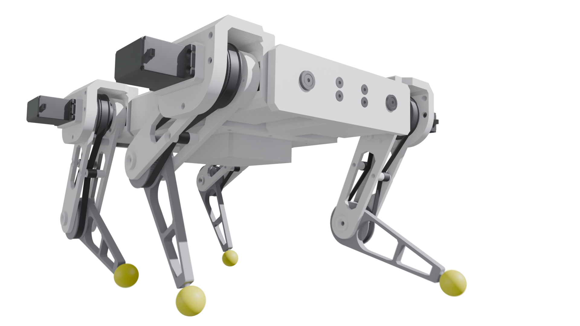
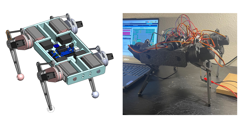
Quadruped robotics has always been a strong area of interest for me. During a recent course, I began the development of my own quadruped system (ARGOS) from the ground up. Given the complexity of such a project and the constraints of a single semester, certain design trade-offs were necessary. However, development is ongoing, and future plans and revisions are extremely exciting.
KINEMATICS:
A basic 12DOF kinematic structure was developed for this system, with 3 motors per leg. Initial work to develop the an analytical inverse kinematics solution for a single leg was simple. The following equations were obtained for each joint.
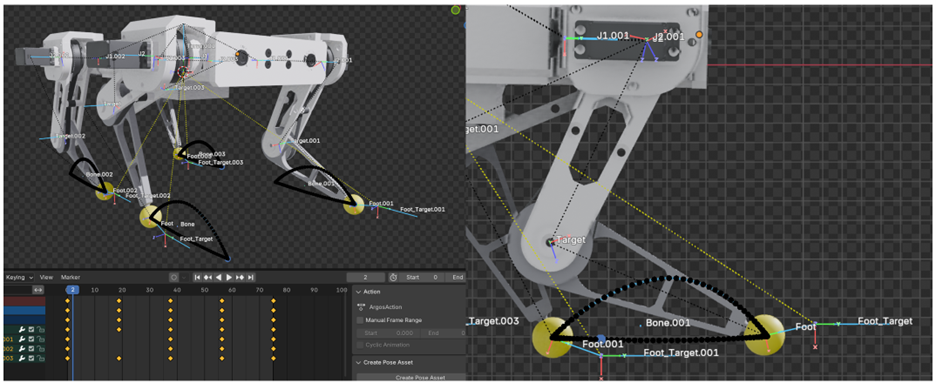
Following the single leg case, a general torso model was developed with a torso frame and 4 local hip frames. Using a roll/pitch/yaw transformation matrix on the torso frame, the distance from the centroid to the origin of an hip frame could be determined. Given an additional vector input from the torso centroid to the foot target position, vector math could be used to determine the necessary (x,y,z) inputs to the individual local hip frames to achieve a specified torso orientation output. These values were then used in the previously determined IK solutions to allow for full torso orientation with a very simple

Theta1 Solution
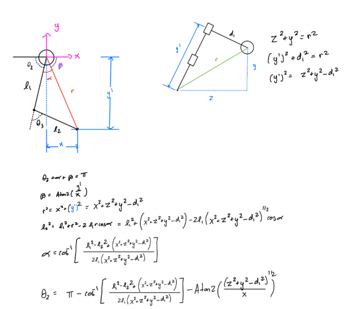
Theta2 Solution
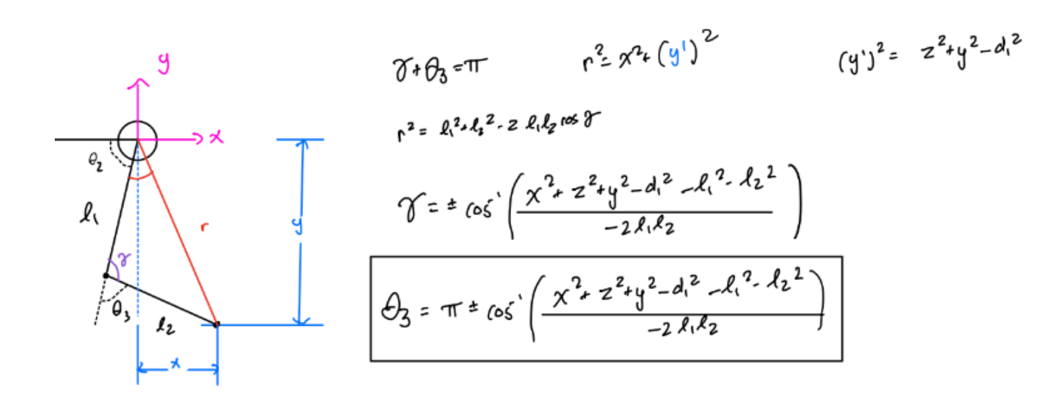
Theta3 Solution
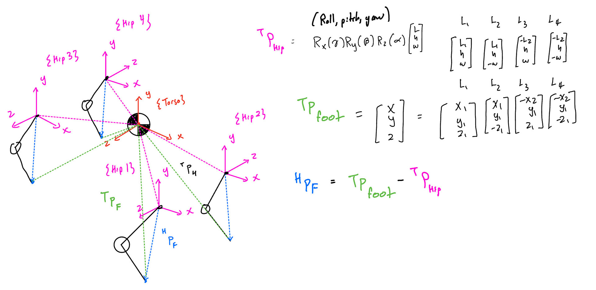
Full Torso IK solution
To avoid redundant kinematics, symmetry was used as much as possible. Each leg fundamentally is comprised of 3 primary vectors. For convenience, the global reference frame is placed coincident with the centroid of the torso.
(1) The p_(torso to hip_i) vector (shown in pink) describes the position of the hip frame within a global reference frame. These vectors are constrained by an offset vector [L, w, h] and the torso orientation matrix. The offset vector is the geometric distances in [x,y,z] from the torso centroid to the hip frames. The torso orientation is given by a set of Euler angles (roll, pitch, yaw), whose combined transformation is a product of the individual rotation matrices. When the torso orientation is in the nominal (0,0,0) pose the rotation matrix simplifies to the identity matrix resulting in the standard [x,y,z] torso offsets. When an orientation is applied, the global position of the resulting hip vectors can be computed.
(2) The second vector of note p_(torso to foot_i) (shown in green) similarly describes the global distance from the torso to the foot. This vector is used for generating foot trajectories of the system. The vector is used in tandem with the generated trajectories (discussed later) to drive the walking stride. If this vector is fixed, the feet will remain in place and torso orientations can be applied resulting in a ‘virtual zero’ center of velocity.
(3) The third and final vector is a fun solution to make the inverse kinematic solution significantly simpler. This vector p_(hip to foot_i) (shown in blue) is simply the vector difference of the p_(torso to hip_i) and p_(torso to foot_i).
p_(hip to foot_i)= p_(torso to hip_i)- p_(torso to foot_i ) eq(1)
The benefit of describing this relative vector is that the inverse kinematic solution becomes much less messy, as the only inputs are the relative [x,y,z] positions of the foot defined from the origin of the hip to the target foot position. Additionally, the system is highly symmetrical and by using simple sign changes, the joint angles for all 12 legs can be computed from these fundamental IK solutions. The symmetry operations were performed using a ‘reflection vector’. This 1x3 vector contains either 1’s or -1’s and is specific to the individual leg. By defining this structure, generic leg functions can be written, and these specific parameters could be passed with the leg struct to calculate the correct angles. An example of these reflection vectors is shown below. This vector is applied to the p_(torso to hip_i) & p_(torso to foot_i ) vectors to produce equivalent transformations. The corresponding inverse kinematic and symmetry work is shown below in figures 4 & 5.
MECHANICAL:
An initial concern with the design of the system involved the actuation method. 12DOF requires 12 motors which quickly becomes very expensive. Cheap hobby servo motors were used to minimize cost; however, these servos have limited torque outputs, and thus the design was scaled around these servo motors using a torque analysis. The structure is unique in its requirement to self-support the weight of its own motors as opposed to traditional serial manipulators. These motors weights contributed the most to the overall mass of the body, and a rough estimation was used to calculate the remaining mass due to housing/electronics. Each actuator produced a peak torque of 0.11Nm. By determining the positions of highest torque load, the maximum allowable leg lengths could be determined (shown below). These lengths were scaled down to allow for sufficient movement power.
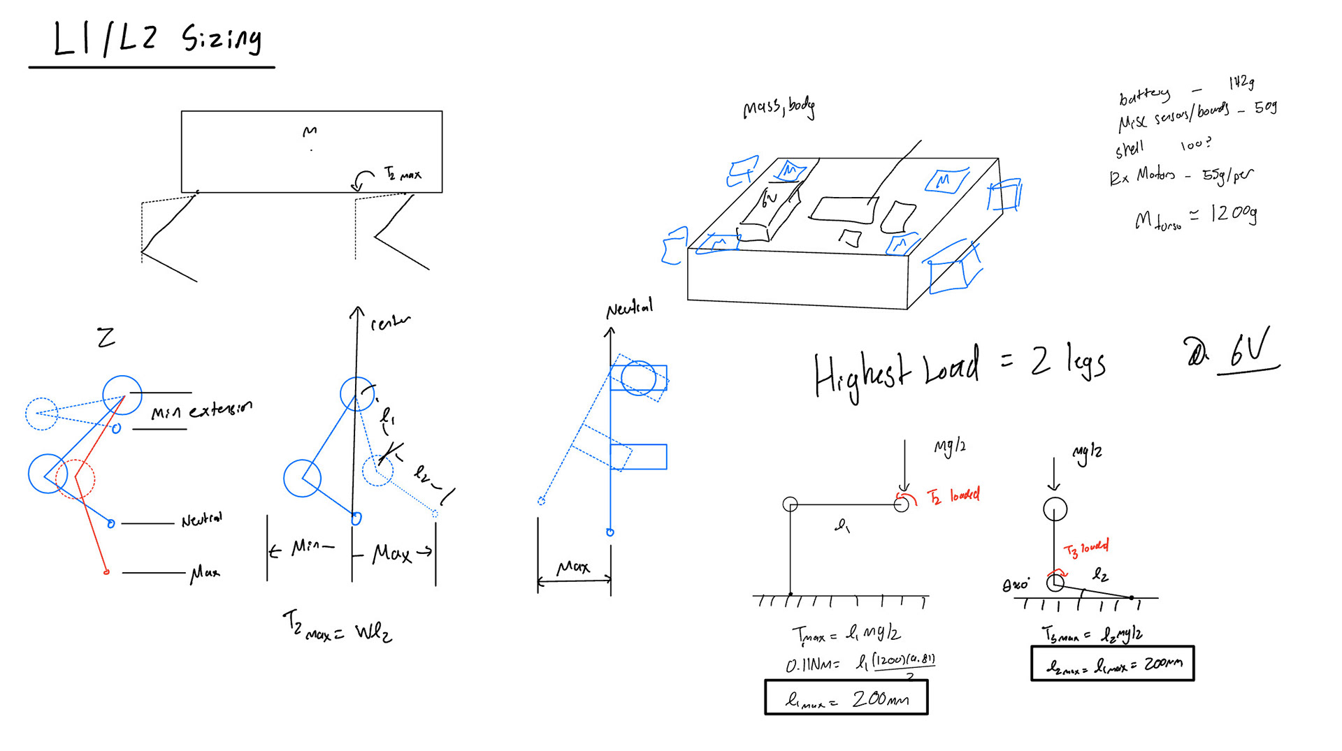
Sample Calculations for Scale / Leg Sizing
After general scale of the project was developed, the leg design started. Given the selected motors low torque, additional inertial effects were avoided by placing the motors as close together as possible. This initial leg design consisted of a 4-bar style linkage (bottom right), however this soon led to restrictive issues with joint limits and also prevented easy placement of a supporting bearing on the end of the leg, leading to bending and unwanted play in the joints. To fix this, an alternative belt design (bottom left) was created. This allowed for unrestricted range of motion, and allowed for the placement of an additional supporting bracket to reduce loading. This significantly improved the workspace as well, but allowing for a full ROM of the third motor.
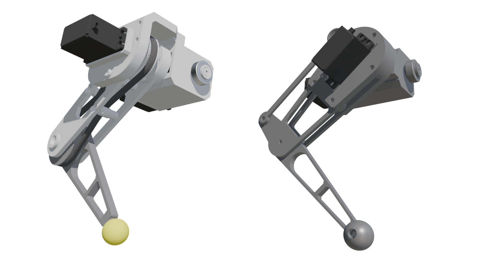
Initial four-bar Leg Design
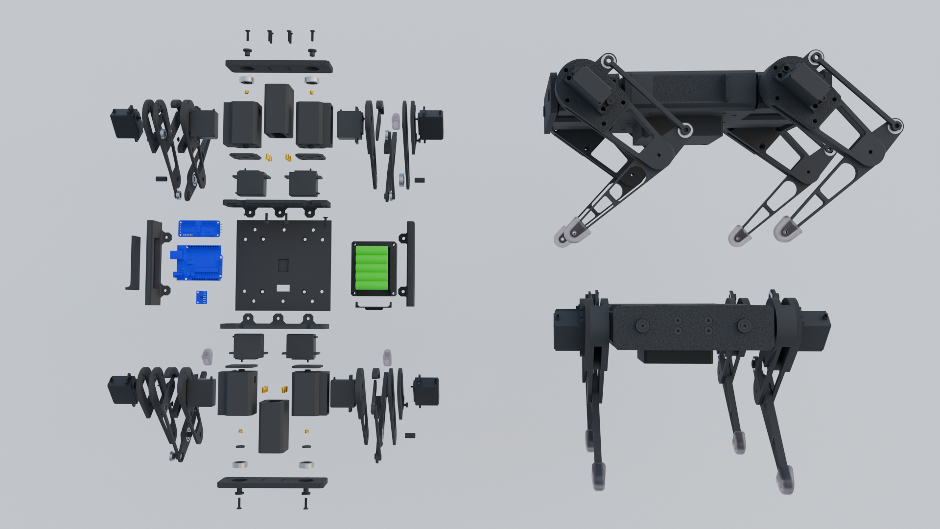
Exploded View
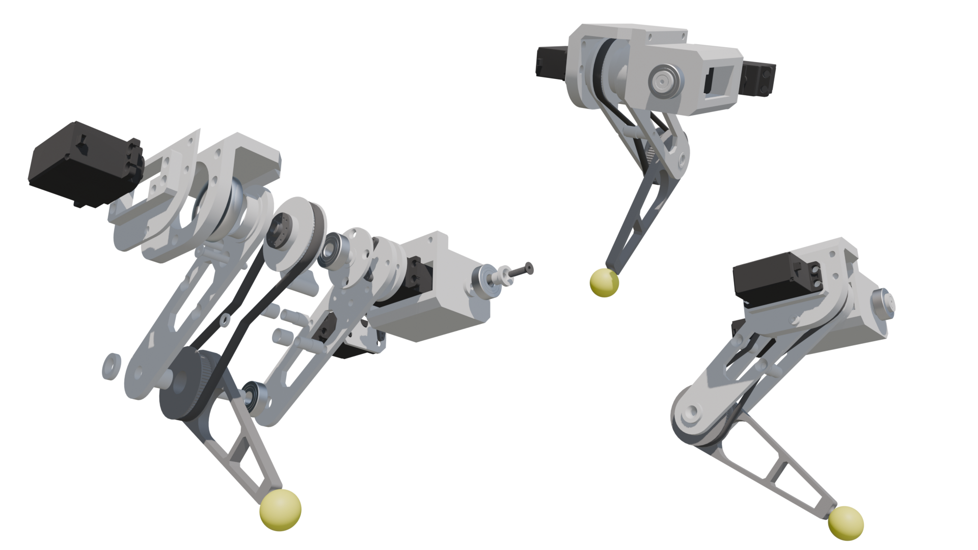
Revised Belt Driven Leg
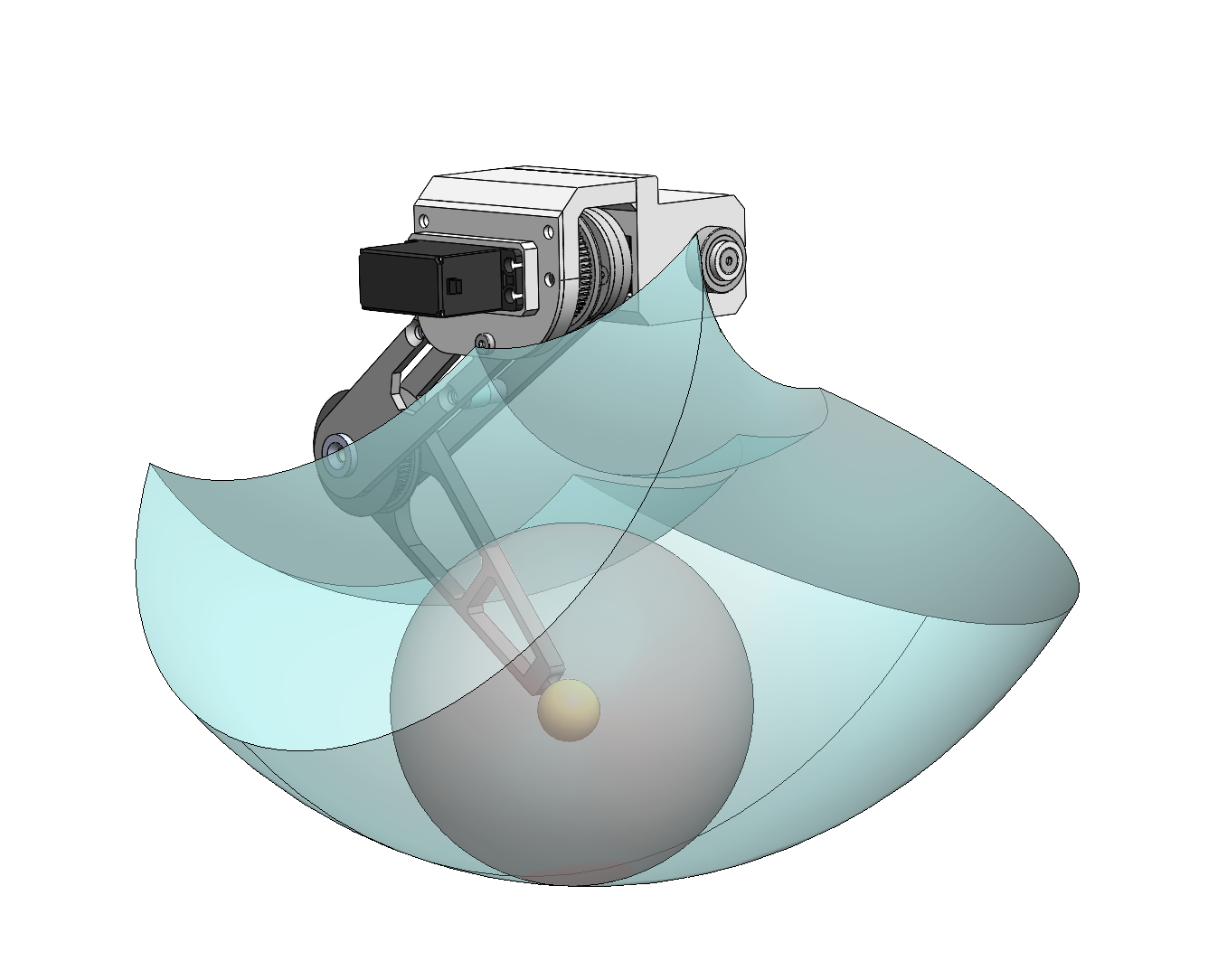
Belt Driven Leg Workspace
PATH PLANNING / CONTROLS:
Traditional quadruped robot walking gaits often rely on a high level path policy that includes a gait strategy and trajectory planner. A main gait library is programmed with a library of gaits such as walking, trotting, etc. These predefined gaits coordinate the general trajectory of each leg. I really want to get some model predictive control going on this in the future, with all of the sensor data argos acquires.

First Walking Test:
Roll Pitch Yaw Test:
While not to the caliber of Boston Dynamics quite yet, the current system does include some slight dynamic adjustments utilizing the IMU. Given the kinematic structure developed, the local foot vectors are functions of roll/pitch/yaw commands. Thus, a control loop can be created where the system constantly aims to drive the IMU readings all to zero. These changing outputs will then drive the local foot vectors and all subsequent joint angles. This approach is fun, but definitely lacking in scalability. It only works for flat level ground, which will not always be the case. Future controls plans include impedance control, which will aim to drive the measured contact forces on all four legs to be the same. However, this isn't currently possible with the cheap servo motors, so better (and more expensive) motors are needed to properly implement something like this.
SOFTWARE:
Full source code can be found here on github.
Argos is controlled via an STM32 breakout board to allow for high speed processing. A GCC-makefile based environment was used to build and compile the code onto the board via the built in ST-Link debugger.
This project was my first chance at getting to work with I²C protocols. Specifically, the main motor driver used was a PCA9685 which allows a 16 channel PWM output. Plenty of arduino libraries existed for this board given its popularity with other makers. However since this project was based in the STM32 environment, I took it as a chance to familiarize myself with how to develop and communicate with I²C devices. I was able to read through the datasheet and pull together the register list with all the necessary register addresses I needed. Using the STM's built in HAL I²C commands, I got all the I2c read/writes working. Once the PMW output parameters were all set, a wrapper 'motor' type was made to handle and used to implement higher level function calls.
The current software layout is very bare bones, and provides the mainly basic movements. Time constraints to finish all the build and assembly prior to software development meant that this section was unfortunately cut short. The current system however is a beneficial foundation for further development.